Settings
Simulation domain
The simulation domain defines the spatial size of the simulation for the selected plan. By default, this is set to the size of the primary planning image, plus any extension needed to encompass the transducer. All sonications within a plan share the same domain size.
After the first sonication has been added, it is possible to adjust the domain size by selecting the ![]()
Resize Simulation Domain Using Cursor button. This automatically toggles on the display of simulation domain, which is displayed as a white box. The size can then be adjusted by using the cursor to drag the white circles on any of the 2D or 3D image views.
The minimum domain size is given by the bounding box around the transducer position (or positions if there is more than one sonication). This can be set by clicking the ![]()
Shrink Domain Size To Minimum Allowable button. If additional sonications are added where the transducer is outside the current domain size, the domain size is automatically expanded.
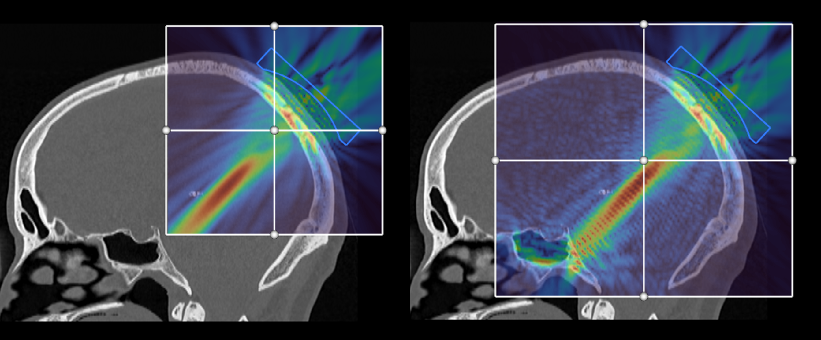
In general, the simulation domain should be set to cover the region of interest, including any bone structures the ultrasound beam may interact with. This is particularly important for lower frequencies, longer focal lengths, or deep targets near the skull surface, where reflections from skull bone on the opposite side of the brain can lead to the formation of standing waves.
In the example below, the simulation domain on the left doesn't include the occipital bone, while the simulation domain on the right does. There is a clear difference in the simulated ultrasound field due to the reflections.
Simulation settings
Simulation settings for each plan can be adjusted in the Settings tab of the plan developer dialog. The settings start with the default values, and any changes apply only to the selected plan (each plan has its own simulation settings).
The General settings specify the most common settings that may be modified.
- Grid points per wavelength: This defines the resolution (grid spacing) used for the simulation. The reference wavelength is calculated using the driving frequency across all sonications, and the reference sound speed (default value of 1540 m/s). A higher number of grid points per wavelength will give a more accurate solution, but will take longer to calculate. The default value of 6 grid points per wavelength provides a good balance between accuracy and compute time for most scenarios.
- Run thermal simulation: Selects whether a thermal simulation is executed (see evaluating plans).
- Link thermal simulations for multiple sonications: Selects whether an independent thermal simulation is conducted for each sonication (un-checked), or whether a single thermal simulation is conducted where the sonications are sequentially applied (checked). In the second case, the final temperature of each sonication is used as the starting temperature of the next, and any additional time between each sonication can be controlled by the cooling time.
Exploratory simulations
Often, a plan will be evaluated several times while the transducer position and sonication parameters are adjusted. In this phase of planning, reducing the number of grid points per wavelength and de-selecting to run the thermal simulation can significantly reduce the computational time.
The Calculated parameters settings define which simulation values are stored in the results file and displayed. By default, the medium segmentation option is checked, and the other options un-checked. The default options are generally suitable for most use cases.
- Medium segmention: The segmentation of the background, soft tissue, and bone used to define the medium properties.
- Pressure phase: The phase of the calculated steady-state pressure field.
- Thermal dose: Thermal dose in cumulative equivalent minutes at 43 degrees (CEM43). Note, for transcranial ultrasound stimulation (TUS), the CEM43 are typically so small (\(\ll\) 1) the returned images appear noisy due to the numerical precision of the calculation.
- Planning images: By default, the primary planning image is only stored in the uploaded planning file, not the downloaded results file. This option also includes the primary planning image in the results file.
The Advanced Settings define additional parameters for advanced users. The default options are generally suitable for most use cases.
- Material property conversion method: Controls the method used to convert the primary planning image to acoustic and thermal material properties. Two options are available:
Head CTandWater. The defaultHead CToption maps the material properties from a CT image and is described in the simulation pipeline. TheWateroption ignores the planning image and assigns the properties of water. This can be useful for modelling the response of a transducer in free-field. - Reference sound speed: Specifies the reference sound speed in m/s used to compute the grid spacing and number of time-steps. The grid spacing is calculated using the reference sound speed, the grid points per wavelength, and the maximum driving frequency across all sonications using \(dx = c_\mathrm{ref} / (f_\mathrm{max} \times \mathrm{PPW})\).
- Output data type: Specifies the data-type used to store the computed pressure and temperature fields in the results file (note, this setting doesn't affect the precision of the calculations). The default option
uint16is generally appropriate. However, the data can also be stored asfloat, for example, if additional precision is required for further processing outside of k-Plan. However, this will double the size of the results file. - Forward planning grid traversals: Sets the number of time-steps used in the forward planning acoustic simulation before extracting the steady-state field. The time is defined as the number of grid traversals across the grid diagonal (defined by the size of the simulation domain) at the reference sound speed.
- Aberration correction grid traversals: Sets the number of time-steps used in the aberration correction acoustic simulation before extracting the element phases via phase conjugation.
- Run aberration correction simulation: For multi-element arrays, this option determines whether the aberration correction simulation is performed.
- Re-scale target pressure: For multi-element arrays, this options determines whether the simulation output is re-scaled so that the target pressure is obtained at the target position.