Transducers
Transducer types
k-Plan supports three types of transducers. The selected transducer type determines which options are visible in the plan developer dialog.
- Single-element transducers with either a spherically-focused (bowl) or circular element. These transducers do not support electronic steering.
- Annular arrays consisting of multiple concentric annuli (either spherically-focused or flat). These transducers allow electronic axial focal steering.
- Multi-element arrays consisting of multiple spherically-focused or circular elements. These transducers allow electronic focal steering and automatic aberration correction.
Additional transducers can be downloaded from the transducer library.
Transducer specifications
Transducer specifications are stored in a k-Plan transducer file with a .ktx extension. This file specifies the properties of the transducer, including the geometry, driving parameter limits, and the visual display of the transducer device and elements within the plan developer dialog.
New transducer specifications can be added via the plan browser dialog by adding a new plan (or selecting to edit an existing plan), selecting Browse next to Transducer, and then selecting Add New. Existing transducer specifications can be removed in the same way.
k-Plan default transducers
Three default transducer specifications are included in k-Plan. These are for demonstration purposes and do not represent any particular physical transducer.
K-PLAN-BOWL-R64-D64-E1: Single-element spherically-focused (bowl) transducer with a 64 mm radius of curvature and 64 mm aperture diameter.K-PLAN-ANNULAR-R64-D64-E8: Annular array transducer with eight equal-area elements with a 64 mm radius of curvature and an overall aperture diameter of 64 mm.K-PLAN-MULTI-R150-D150-E128: Phased-array transducer with 128 individual 5 mm diameter elements evenly distributed over the surface of a bowl (using Fermat's spiral) with an overall 150 mm radius of curvature and 150 mm aperture diameter.
These transducers specifications are set to have a driving frequency range from 200 to 600 kHz, with a default of 250 kHz.
Transducer coordinate system
The transducer specification defines the position of the transducer elements relative to the transducer coordinate system. For single-element and annular array transducers, the centre of each element is positioned at the origin of the transducer coordinate system, with the transducer beam axis oriented in the negative z-direction. The image below shows the K-PLAN-BOWL-R64-D64-E1 transducer relative to the transducer coordinate axes.
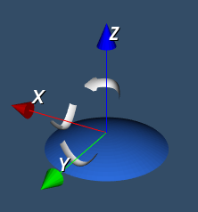
For single-element and annular array transducers, this means the radiating surface of the transducer is aligned with the origin of the transducer coordinate system. For some transducers, there may be other structures in front of the radiating surface, for example, lenses or coupling layers. This means the radiating surface as modelled in k-Plan may actually be inside the physical transducer body (see image under Transducer display). For annular array transducers, the focal distance parameter may also be referenced to a different position, for example, the transducer exit plane.
For transducers that have a cable assembly, the convention in k-Plan is that this is orientated in the negative x-direction as shown in the image below.
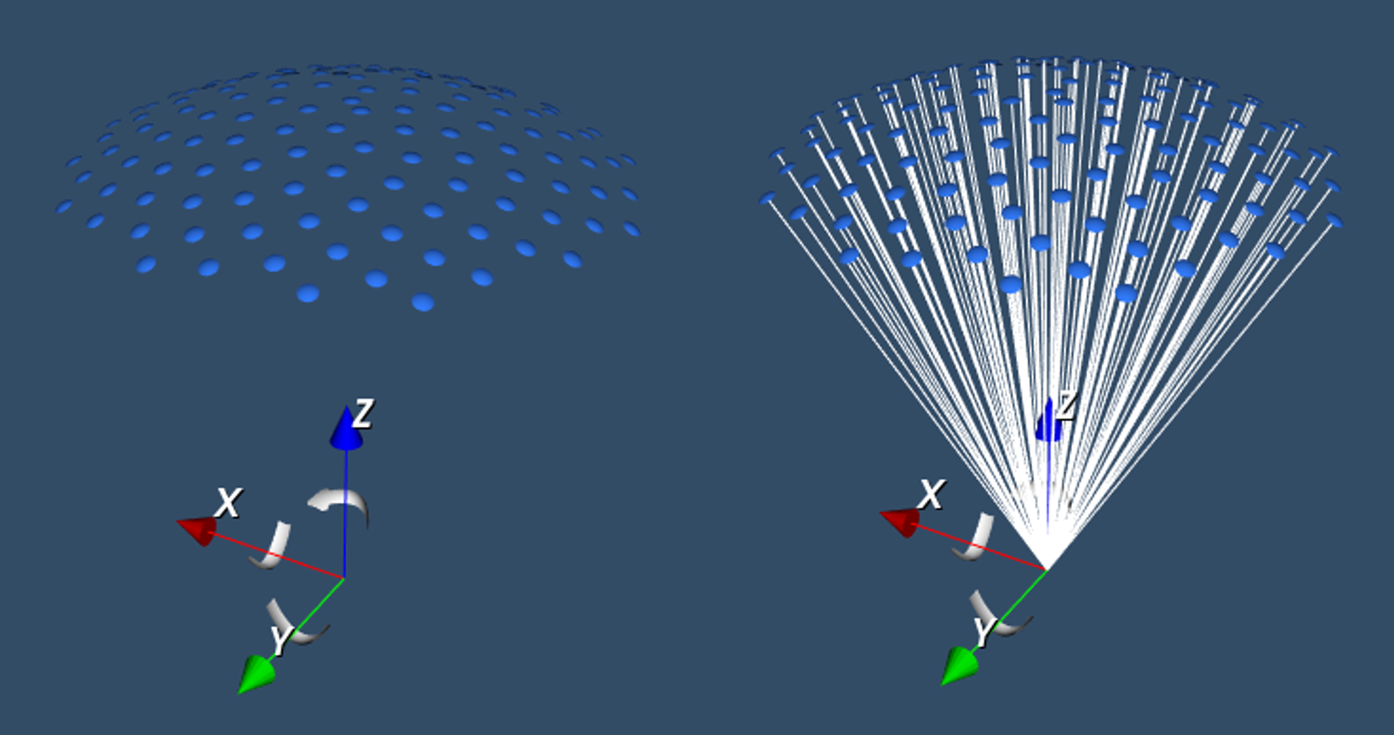
For multi-element arrays, the elements are typically positioned in 3D space, with the origin of the transducer coordinate system aligned with the geometric focus of the array. The image below shows the position of the elements for the K-PLAN-MULTI-R150-D150-E128 transducer relative to the transducer coordinate axes. The image on the right also shows the element normals which are focused on the coordinate origin.
Transducer position transform
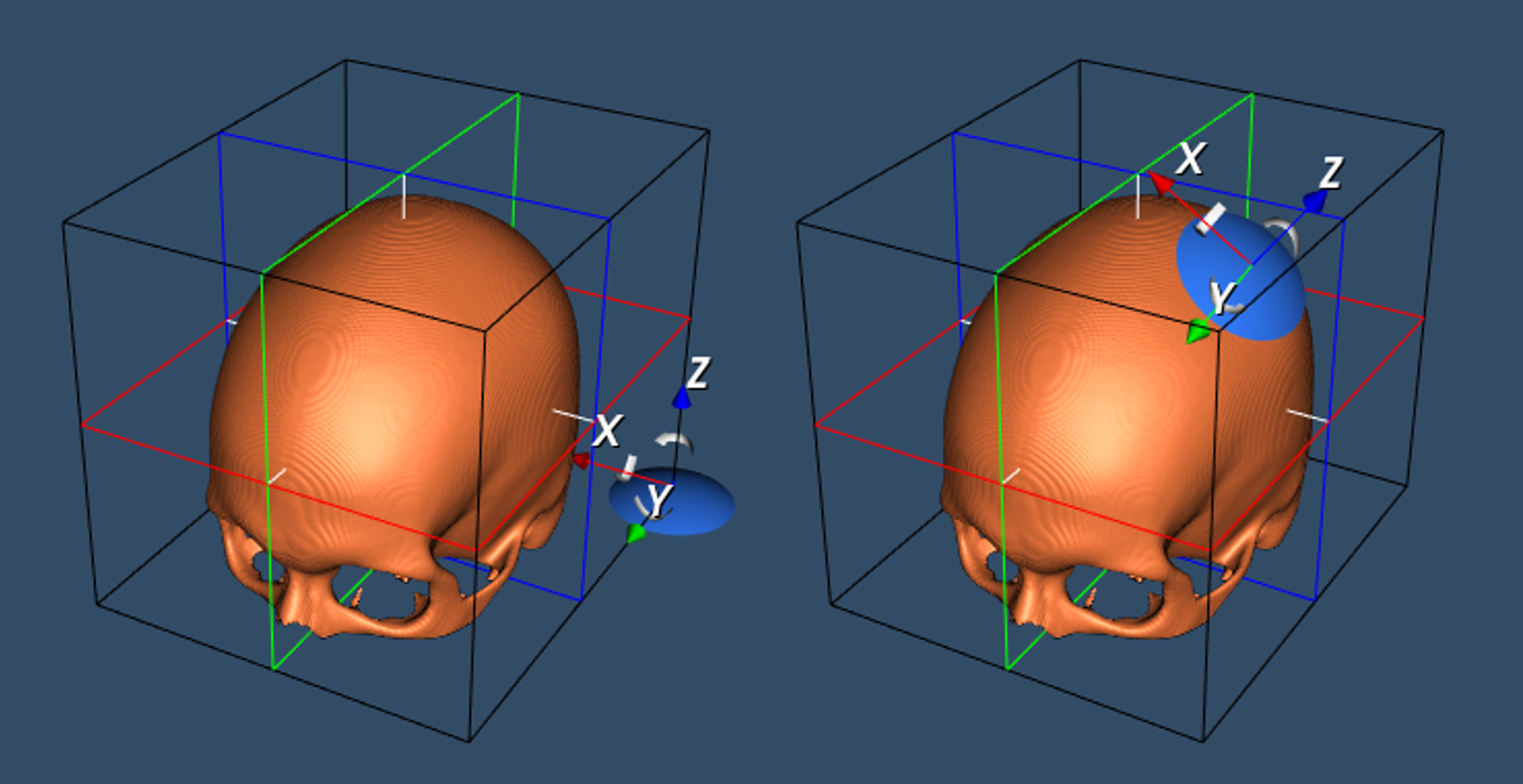
The position of the transducer is defined as an affine transformation between the k-Plan world coordinates and the transducer coordinate system. If the identity transform is used, the two coordinate systems will be aligned at the LPI corner of the primary planning image. The image below shows the K-PLAN-BOWL-R64-D64-E1 transducer relative to the MNI template skull with the identity transform (left), and positioned for a cortical target (right).
Each sonication is associated with a specific transducer position. This means that each plan may have multiple transducer positions.
Placing the transducer
There are several options for specifying the initial position of the transducer for a new plan: using the transducer wizard, using the cursor to place the transducer manually, or importing the position from an external file.
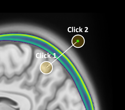
To place the transducer automatically using the transducer wizard, select the Automatically Place Transducer Using One Alt-Click ![]() button in the
button in the Planning tab. On one of the 2D image views, navigate until the desired target is in view, then hold the Alt key and use the left mouse button to click on the image at the desired target location. This sets both the target position and the transducer pivot point relative the k-Plan world coordinates.
After setting the target point, the transducer wizard then automatically computes the position of the transducer using the following steps:
-
Image Preparation: The primary planning is smoothed to reduce noise and make surface extraction more reliable, and down-sampled to speed up subsequent calculations.
-
Surface Extraction: Skin and skull surfaces are extracted from the processed image using a flying edges algorithm with thresholds of 950 kg/m3 (skin) and 1150 kg/m3 (bone). The thresholds are converted to Hounsfield units based on the CT calibration.
-
Optimal Skull Position: The skull surface is searched for the best position that satisfies three criteria:
- The angle between the skull surface and the line to the target is as small as possible, and within a certain maximum angle (typically 10 degrees)
- The position is within a maximum distance from the target (typically 40mm)
- The angle between the line to the target and the vertical axis is within a certain maximum angle (typically 120 degrees)
-
Skin Surface Projection: Once the optimal skull position is found, a line is projected from the target through this skull point onto the skin surface. The transducer is then positioned a short distance away from the skin surface point (typically 10mm) along the line from the target. This leaves a gap for coupling while maintaining the correct orientation towards the target.
If the skull is too far from the target, the angle at the skull surface is too steep, or the distance between the skull and skin surface is too large, an error message is shown.
The entire process typically takes a few seconds, depending on the resolution of the primary planning image. Once complete, the transducer will appear positioned in the viewer, oriented towards the selected target. This position can then be fine-tuned manually if needed.
Remember, while the transducer wizard is designed to find a potential transducer position, you must always review and verify the placement before proceeding with treatment planning.
Placing the transducer manually
To place the transducer manually using the cursor, select the ![]()
Place Transducer Using Alt-Click button in the Planning tab. On one of the 2D image views, hold the Alt key, and then use the left mouse button to click on the image. This sets the transducer pivot point relative the k-Plan world coordinates.
The pivot point defines the negative z-axis of the transducer coordinate system. For single-element and annular array transducers, this is equivalent to setting the orientation of the beam axis (i.e., the direction in which the transducer is pointing).
Hold the Alt key, and then use the left mouse button to click on the same image a second time. This sets the origin of the transducer coordinate system relative the k-Plan world coordinates.
To cancel placing the transducer, de-select the ![]()
Place Transducer Using Alt-Click button.
For annular-array transducers, the distance between the origin and the pivot points is used to set the focal distance, provided this distance is within the minimum and maximum focal distance allowed by the transducer. If the origin-pivot distance is greater than the maximum allowable focal distance, the focal distance is set to the maximum value (similarly for the minimum value).
For multi-element arrays that are not axisymmetric about the z-axis, additional adjustment to the transducer orientation will likely be needed. It can sometimes be helpful to turn off other image overlays and tools when placing the transducer.
Importing the transducer position
The transducer position transform can be imported by selecting the ![]()
Import Transducer Position Transform From File button in the Planning tab. Several file formats are currently supported. The k-Plan file format uses a HDF5 container as shown in creating a transducer position file. Transducer positions can also be imported from the Brainsight and Localite neuronavigation systems.
After selecting the file format from the dropdown box, the file to load can be selected by clicking the Select File button. This will populate a dropdown list of the transforms stored in the file. Select the desired transform, and then click load. This will set the current position of the transducer in the Planning tab. A sonication can then be added using this transducer position.
When importing transducer positions from other sources, remember that the position transform in k-Plan maps between k-Plan world coordinates and the transducer coordinate system. For single-element and annular array transducers, the transducer coordinate system is aligned with the radiating surface. This may not be the same transducer reference position used by other software tools.
Importing and exporting positions from Brainsight
k-Plan supports importing and exporting transducer positions from Brainsight. If importing positions, the Brainsight export must be set to use "Brainsight" coordinates (not MNI). Brainsight and k-Plan must also use the same primary planning image (anatomical dataset), otherwise the imported position will not be correct. This is because the imported transform must be converted from Brainsight coordinates (RAI) to k-Plan coordinates (LPI), which uses the size of the primary image. The same is true when exporting positions from k-Plan for use in Brainsight.
Importing positions from Localite
k-Plan supports importing instrument marker positions from Localite. Select the desired GUMMarkers file from the appropriate GUMMarkers folder in the Localite session data. Note, it is only possible to import marker positions from a session that uses NIFTI image data (not DICOM or MNI) as this specifies the transform in RAS format. Localite and k-Plan must also use the same primary planning image (anatomical dataset), otherwise the imported position will not be correct. This is because the imported transform must be converted to account for the origin of the k-Plan world coordinates.
Creating a transducer position file
The code snippet below shows how a transducer position file in k-Plan format can be created using MATLAB. The transform is saved in a HDF5 file with a .kps extension. This example creates two transforms that move the transducer 10 cm in the positive x or y directions relative to the k-Plan world coordinates. HDF5 files can also be created in many other programming languages.
MATLAB code to create k-Plan transducer position file
% create affine transform matrix to translate 10 cm in x
translate_x = eye(4);
translate_x(1:3, 4) = [0.1, 0, 0];
translate_x_label = 'Translate X';

% create affine transform matrix to translate 10 cm in y
translate_y = eye(4);
translate_y(1:3, 4) = [0, 0.1, 0];
translate_y_label = 'Translate Y';

% save transform matrices to HDF5 file
filename = 'position-transform.kps';
h5create(filename, '/1/position_transform', [4, 4, 1], 'DataType', 'single');
h5write(filename, '/1/position_transform', single(translate_x));
h5writeatt(filename, '/1', 'transform_label', translate_x_label, 'TextEncoding', 'system');

h5create(filename, '/2/position_transform', [4, 4, 1], 'DataType', 'single');
h5write(filename, '/2/position_transform', single(translate_y));
h5writeatt(filename, '/2', 'transform_label', translate_y_label, 'TextEncoding', 'system');

% set required file attributes
h5writeatt(filename, '/', 'application_name', 'k-Plan', 'TextEncoding', 'system');
h5writeatt(filename, '/', 'file_type', 'k-Plan Transducer Position', 'TextEncoding', 'system');
h5writeatt(filename, '/', 'number_transforms', uint64(2));
The transforms are stored in 1 x 4 x 4 datasets called position_transform stored in single-precision in number groups (starting from 1). Note, the file creation from MATLAB automatically converts from column-major to row-major order such that the generated dataset has dimensions of 1 x 4 x 4. Additional file attributes must also be defined as shown above.
Adjusting the transducer position using the cursor
After the transducer has been placed, the position can be adjusted using the cursor or via the transducer positioning panel. To adjust the position using the cursor, select the ![]()
Adjust Transducer Position Using Cursor button. This will allow the origin of the transducer coordinate system and the pivot point (which defines the direction of the negative z-axis) to be adjusted using the cursor on any of the 2D views.
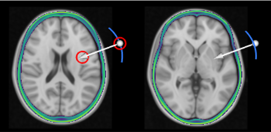
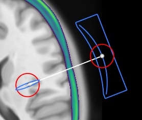
The origin and pivot points are displayed on the image views using a white arrow as shown below. These points can be moved using the mouse cursor. If the end points lie on (or near) the displayed image slice, these points are highlighted using a red circle (left panel below). Otherwise, only the arrow is visible (right panel below). In both cases, moving the end points of the positioning arrow on any of the 2D views will automatically move these points into the displayed image plane.
For annular-array transducers, the distance between the origin and the pivot points is used to automatically adjust the focal distance, provided this distance is within the minimum and maximum focal distance allowed by the transducer. If the display of the transducer focus is switched on, the position of the displayed focal ellipsoid will move automatically as the transducer origin and pivot points are adjusted.
Adjusting the transducer position using the positioning panel
The transducer position can also be adjusted using the transducer positioning panel. To display this panel, select the ![]()
Adjust Transducer Position button. This allows the origin of the transducer coordinate system and the pivot point (which defines the direction of the negative z-axis) to be directly entered as positions relative to k-Plan world coordinates.
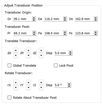
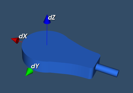
The transducer position can also be adjusted using the jog buttons under Translate Transducer. If Global Translate is selected, position adjustments (dX, dY, dZ) are made relative to the k-Plan world coordinates. For example, stepping in the positive x-direction (up arrow) will move the transducer towards the right of the image. If Global Translate is not selected, position adjustments are made relative to the transducer coordinates. For example, stepping in the negative z-direction (down arrow) will move the transducer in the direction of the vector joining the origin and pivot points. This is the same direction as the positioning arrow displayed when ![]() is selected.
is selected.
If Lock Pivot is not selected, any translations will be applied to both the origin and pivot points. If Lock Pivot is selected, then the translations are only applied to the origin point. This is useful for making changes to the transducer position without changing the pivot point.
The transducer orientation can similarly be adjusted using the jog buttons. If Rotate About Transducer Pivot is selected, the rotation adjustments (rX, rY, rZ) are performed about the transducer pivot point. If Rotate About Transducer Pivot is not selected, the rotations are performed about the transducer origin.
When hovering over the jog buttons, axis are displayed in 3D view to show the directions for the position and orientation adjustment. The position and orientation of these axis depend on the settings for Global Translate and Rotate About Transducer Pivot.
Transducer display
In the Planning tab, different components of the transducer can be displayed by toggling the Display Settings in the left toolbar.

View Transducer: Displays the device STL file which represents the complete transducer.
View Transducer Elements: Displays the element STL file which represent each transducer element.
View Transducer Focus: Displays an ellipse-shaped focal marker at the position of the transducer focus (single element and annular array transducers only). As mentioned above, the distance between the origin and the pivot points is used to automatically adjust the focal distance, provided this distance is within the minimum and maximum focal distance allowed by the transducer. For an existing sonication, the focal distance can also be modified using the sonication table. Changes made via the sonication table can be visualised by right-clicking on the sonication and re-loading the transducer position. The size of the displayed focal ellipse (length and width) is automatically computed based on the focal distance and the properties of the transducer (aperture diameter and default frequency). These calculations are based on approximate formula valid in free-field (water). The position of the actual focus after propagating through the skull may be different.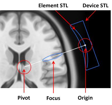

View Transducer Beam Axis: Displays a white line connecting the element positions and the transducer origin in the 3D view.
Snap View To Transducer Axes: Changes the orientation of all three 2D image views to align with the transducer coordinate system instead of the default k-Plan world coordinates. The views are relabeled as XY, XZ, and YZ, corresponding to the transducer coordinate planes. This feature makes it easier to visualise how the transducer focus overlaps with brain targets, as the image planes are now orthogonal to the transducer's orientation rather than the anatomical planes.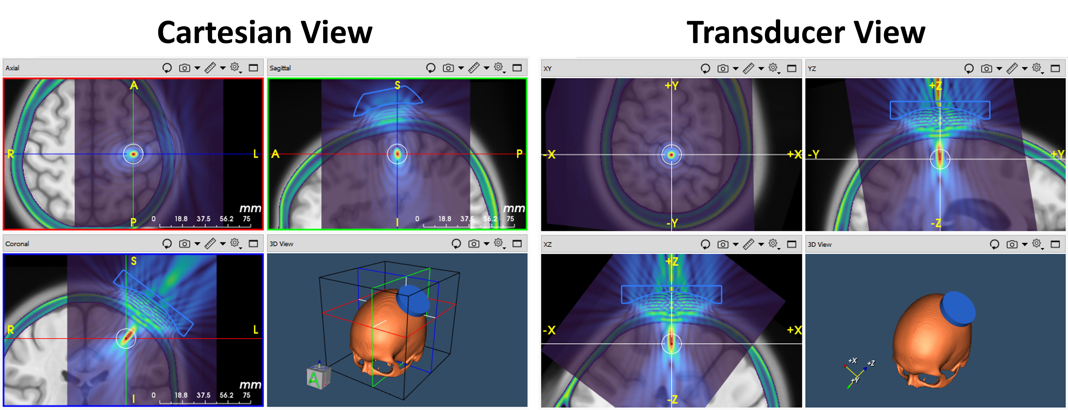
Exporting the transducer position
The transducer position transforms used in each sonication can be exported to an external file. The export dialog can be accessed via the Export button in the icon bar. See Importing the transducer position for details of the file types supported.