Transducer library
Transducer definitions
Select the transducer model name below to download the transducer definition.
| Manufacturer | Model | Type | Elements | Frequency | ROC* | AD* | FDO* | FD* |
|---|---|---|---|---|---|---|---|---|
| k-Plan | BOWL-R64-D64-E1 | Single Element | 1 | 200-600 kHz | 64 mm | 64 mm | - | - |
| k-Plan | DISC-D38-E1 | Single Element | 1 | 200-600 kHz | - | 38 mm | - | - |
| k-Plan | ANNULAR-R64-D64-E8 | Annular Array | 8 | 200-600 kHz | 64 mm | 64 mm | 8.57 mm | -3 dB |
| k-Plan | MULTI-R150-D150-E128 | Multi-Element | 128 | 200-600 kHz | 150 mm | 150 mm | - | - |
| NeuroFUS | CTX-250-2 | Annular-Array | 2 | 200-300 kHz | 63.2 mm | 64 mm | 6.33 mm | -3 dB |
| NeuroFUS | CTX-250-4 | Annular-Array | 4 | 200-300 kHz | 63.2 mm | 64 mm | 10.82 mm | -3 dB |
| NeuroFUS | CTX-500-2 | Annular-Array | 2 | 400-600 kHz | 63.2 mm | 64 mm | 6.33 mm | -3 dB |
| NeuroFUS | CTX-500-4 | Annular-Array | 4 | 400-600 kHz | 63.2 mm | 64 mm | 10.82 mm | -3 dB |
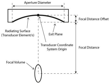
*ROC: radius of curvature, AD: aperture diameter, FDO: focal distance offset, FD: focal distance defined using the centre of the -3 dB focal volume (-3 dB) or the spatial peak pressure (pmax).
A diagram showing the transducer nomenclature for an annular array is shown below. For annular array and multi-element transducers, the radius of curvature (ROC) and aperture diameter (AD) refer to the overall aperture of the array.
For annular array transducers, the focal distance offset (FDO) defines a reference distance on the beam axis of the transducer from which the focal distance measurements are defined (see diagram below). This is typically the exit plane of the transducer. Exact values for each transducer definition are given in the table above. The focal distance is then defined as the distance from the focal distance offset to the focus, where the position of the focus is defined using either (i) the centre of the -3 dB focal volume, or (ii) the position of the spatial peak pressure.
Note, for single element and annular array transducers, the origin of the transducer coordinate system is typically defined at the centre of the radiating surface of the transducer as shown in the diagram below (not the transducer exit plane). Transducer position transforms are defined relative to this point.
Adding a transducer definition to k-Plan
To add a transducer definition to k-Plan, first navigate to the plan browser dialog (see the quick start guide). Select Add New to add a new plan, select Browse to open the transducer browser dialog, then click on Add New and select the downloaded .ktx file. Transducer definitions can also be deleted from the transducer browser dialog.